



Custom Plastic Housing Injection Molding
DeepMould provides custom plastic housing injection molding using PA66 material, with a focus on complex openings, mounting holes, and side locking features. DFM review, side-action mold design, and Moldflow analysis help assess part geometry, filling behavior, and demolding requirements before tooling is finalized.
- Fast Delievery
- Quality Assurance
- 24/7 Customer Service
Description
1.Project Overview
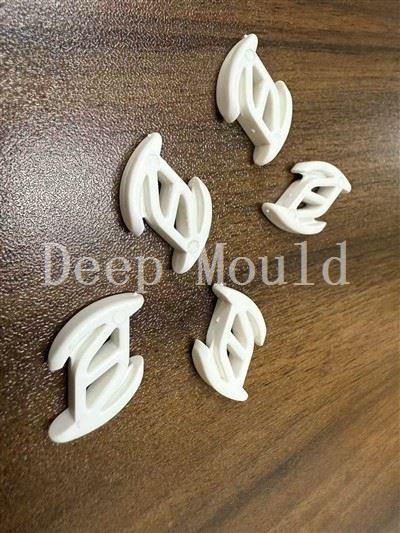
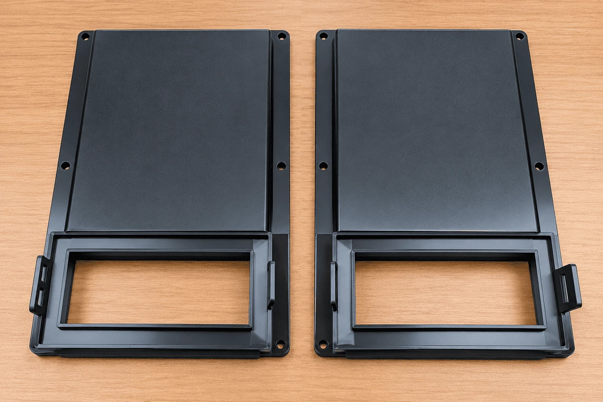
This project concerns a custom injection-molded plastic housing manufactured from POLIMID A SG NATURALE, a PA66 molding grade. The component has a broad planar body, a rectangular opening at one end, mounting holes around the perimeter and projecting locking features along the sides. These details make the housing more demanding than a simple open tray: the tooling must form the large surface while providing controlled release at the opening and the side features.
The project documentation contains actual molded-part photographs, core and cavity tooling photographs, a DFM review, two filling simulation cases, a mold assembly photo set, a heat-treatment inspection record and a machine-interface drawing. The supplied PA66 technical data sheet and SWG 1.2767 steel reference are used below where they are relevant to design and processing. Values from a supplier data sheet are identified separately from CAE results and measured inspection records.
The purpose of this page is to show the engineering decisions associated with a housing of this geometry and the manufacturing information available for this project. It is not a substitute for a controlled drawing or an approved mold qualification report. Dimensions, production quantity, cavity count and final cycle time are omitted because they cannot be established reliably from the supplied documents.
2.Plastic Housing Geometry
• The large external face is the dominant visible surface of the housing. It is interrupted by perimeter mounting holes and a recessed transition toward the rectangular opening. These transitions influence the position of the parting line and the amount of mold steel required around the opening. The tooling also has to reproduce the side locking features without damaging them during demolding.
• The opening requires a consistent edge profile and sufficient steel support in the surrounding cavity and core. Sharp transitions, thin steel projections and abrupt changes in the molding surface are potential tool-maintenance concerns. The part geometry should therefore be checked as a complete assembly: any adjustment made for mold construction must still preserve the clearance and engagement of the housing with its mating component.
• The flat panel region should be assessed for thickness distribution, sink, warpage and local stress concentration. A visually flat molded surface does not guarantee dimensional flatness under all molding conditions. Gate position, packing response, cooling layout and material shrinkage all affect the finished shape. No flatness tolerance or wall-thickness value is assigned here because the supplied images do not provide a controlled dimensional specification.
3.DFM Review: Parting Line, Slider and Steel Condition
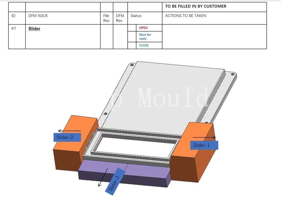
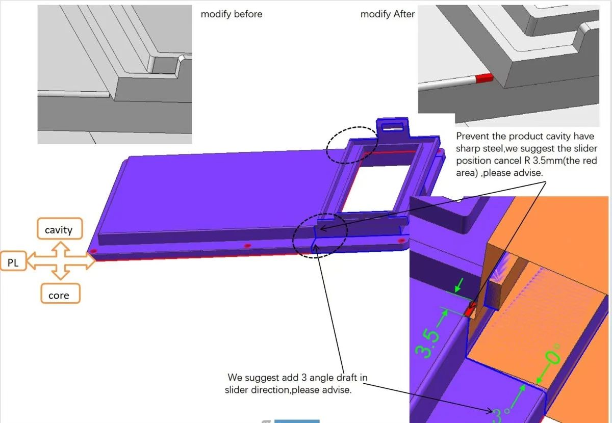
• The DFM drawing identifies the parting line between the cavity and core and calls attention to the side-action area. A proposed 3° draft angle is shown in the slider movement direction. This recommendation is intended to improve release of the side feature as the slider retracts. The angle must be checked against the mating part and the functional engagement length; adding draft without reviewing the assembly could alter the retention or fit.
• The same review identifies a local R3.5 mm region that may create a sharp or insufficiently supported steel condition. The engineering comment proposes removing or changing the local radius at the slider-related position. The intent is to reduce a fragile steel feature, improve machining access and lower the likelihood of local damage during production or maintenance. The drawing records a proposed modification; it does not, by itself, prove that the customer approved the change or that it was implemented in the final tool.
• A practical DFM release should confirm the approved CAD revision, slider travel direction, minimum shut-off contact, draft requirements, parting-line appearance and dimensional interfaces. These checks are especially important around the rectangular opening, where small changes in the steel geometry can affect both the molded edge and the moving tool component.
4.Mold Design and Side-Action Construction
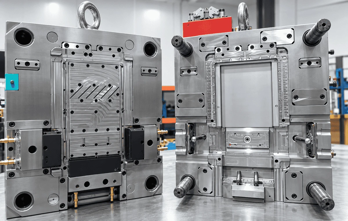
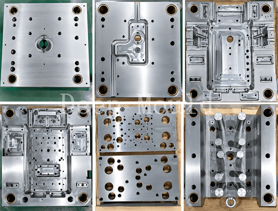
The mold photographs show a complete tooling assembly with core and cavity sides. Around the molded opening, the tool uses machined steel features that must align when the mold closes. Guide components, locating surfaces and moving mechanisms are visible in the photographs. The tooling design should maintain repeatable registration between these elements while leaving sufficient access for fitting and servicing.
Side-action features introduce additional interfaces compared with a straight-pull mold. The slider must reach its fully closed position before injection, remain supported during cavity pressure and retract far enough for the molded feature to clear. The shut-off surfaces require controlled fitting, because excessive clearance may cause flash while excessive interference can produce wear or galling. The release path must also avoid dragging against the PA66 housing after the main mold opens.
Ejection must be considered together with side-action withdrawal. The housing includes a broad panel and several local features; the ejector layout should distribute the release force without concentrating it on a thin wall or the edge of the opening. The exact ejector locations are not stated in the documents, so the discussion here addresses the required engineering checks rather than claiming a particular ejection sequence.
Tooling photographs and hardware
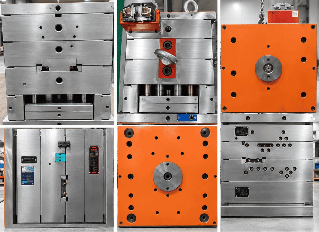
The photo set also documents the external mold plates, mounting interfaces and YUDO-branded hot-runner-related equipment. These are useful references for mold construction and assembly, but the photographs alone do not establish a confirmed gate count, hot-runner circuit layout or production molding cycle. Such details should be taken from the final mold design and trial records when available.
5.Moldflow Review: Flow-Front Temperature
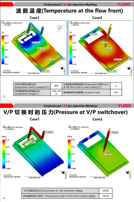
Two cases were evaluated using Autodesk Moldflow Insight. The analysis uses a melt temperature of 280°C and reports a maximum flow-front temperature of 281.9°C for Case 1 and 280.5°C for Case 2. The reported temperature difference across the principal surface is approximately 2°C, and the supplied summary marks the flow-front temperature condition as acceptable. These numbers describe the modeled filling behavior, not a direct measurement of the melt inside a running production mold.
The temperature map is useful because the housing has a large planar area and a frame-like opening. Flow has to progress around the opening and through changes in section. Local differences in flow-front temperature may affect filling balance and the position of knit or weld regions. A nearly uniform front temperature is helpful, but it should be evaluated with the complete simulation results and the part requirements rather than treated as a stand-alone approval.
6.Moldflow Review: V/P Switchover Pressure
The supplied simulation reports pressure at V/P switchover of 65.16 MPa for Case 1 and 60.39 MPa for Case 2. Case 2 therefore shows a lower modeled switchover pressure by 4.77 MPa under the conditions used for the analysis. The document also lists hot-runner pressure losses of 24 MPa and 10 MPa for the two cases. These results suggest that the alternative arrangement changes the pressure demand in the filling system.
|
Simulation output |
Case 1 / Case 2 |
|
Maximum flow-front temperature |
281.9°C / 280.5°C |
|
Pressure at V/P switchover |
65.16 MPa / 60.39 MPa |
Hot-runner pressure drop 24 MPa / 10 MPa
|
Analysis melt temperature |
280°C / 280°C |
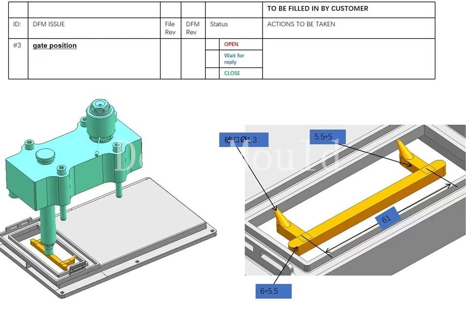
The lower predicted pressure in Case 2 is relevant to gate and runner evaluation, but the best configuration cannot be selected from pressure alone. Gate vestige location, cosmetic requirements, weld-line positions, air entrapment, packing behavior and dimensional stability should be reviewed before the tool design is frozen. The provided image does not show all downstream analyses, so no unsupported claim is made about warpage, shrinkage distribution or final gate approval.
For production validation, the CAE assumptions should be compared with actual material drying, melt temperature, mold temperature, fill time, injection pressure and measured part dimensions. A discrepancy between the simulated and observed filling pattern may indicate differences in process conditions, material behavior or tool geometry.
7.PA66 Material Selection and Process Window
The confirmed resin for this project is POLIMID A SG NATURALE, a standard-viscosity PA66 injection-molding grade. According to the supplied manufacturer data sheet, its density is 1.14 g/cm³, melting point is 260°C and typical average mold shrinkage is 1.4–1.8%. The same sheet gives a tensile strength at yield of 85 MPa and tensile modulus of 3,000 MPa. These values are reference properties of the grade; they are not results of tensile tests performed on this housing.
|
PA66 supplier property |
Typical or recommended value |
|
Density |
1.14 g/cm³ |
|
Melting point |
260°C |
|
Average mold shrinkage |
1.4–1.8% |
|
Tensile strength at yield |
85 MPa |
|
Tensile modulus |
3,000 MPa |
|
Drying recommendation |
At least 3 hours at 90–100°C |
|
Melt temperature recommendation |
260–285°C |
|
Mold temperature recommendation |
70–90°C |
PA66 processing requires moisture control. The supplier recommends drying for at least three hours at 90–100°C before molding. The recommended melt temperature range is 260–285°C and mold temperature range is 70–90°C. These are starting points for process development, not a record of the exact machine settings used to manufacture the photographed parts. Actual settings depend on machine capability, runner configuration, part thickness and filling response.
The supplier shrinkage range should be considered during cavity-size development, but a single percentage cannot reliably describe every direction of a housing with an opening, ribs and side features. Packing pressure, local wall thickness and cooling differences can create nonuniform dimensional changes. The correct approach is to compare molded samples with the approved drawing, review deviations by feature and adjust process conditions or tooling only after identifying the cause.
The material data sheet also states that food or medical use should not be assumed without specific approval. No such application is claimed for this housing. Likewise, the material data alone does not establish a finished-part flame classification, chemical resistance requirement or long-term performance in the customer end-use environment.
8.Steel Reference and Heat Treatment Inspection
The project includes a technical sheet for SWG 1.2767 mold steel. This reference can be used to review general steel properties and the intended tooling material. A separate heat-treatment report identifies the inspected workpieces as grade 2343, not 1.2767. The two documents therefore should not be merged into one material certification or used to claim that the measured hardness applies to every 1.2767 component in the mold.
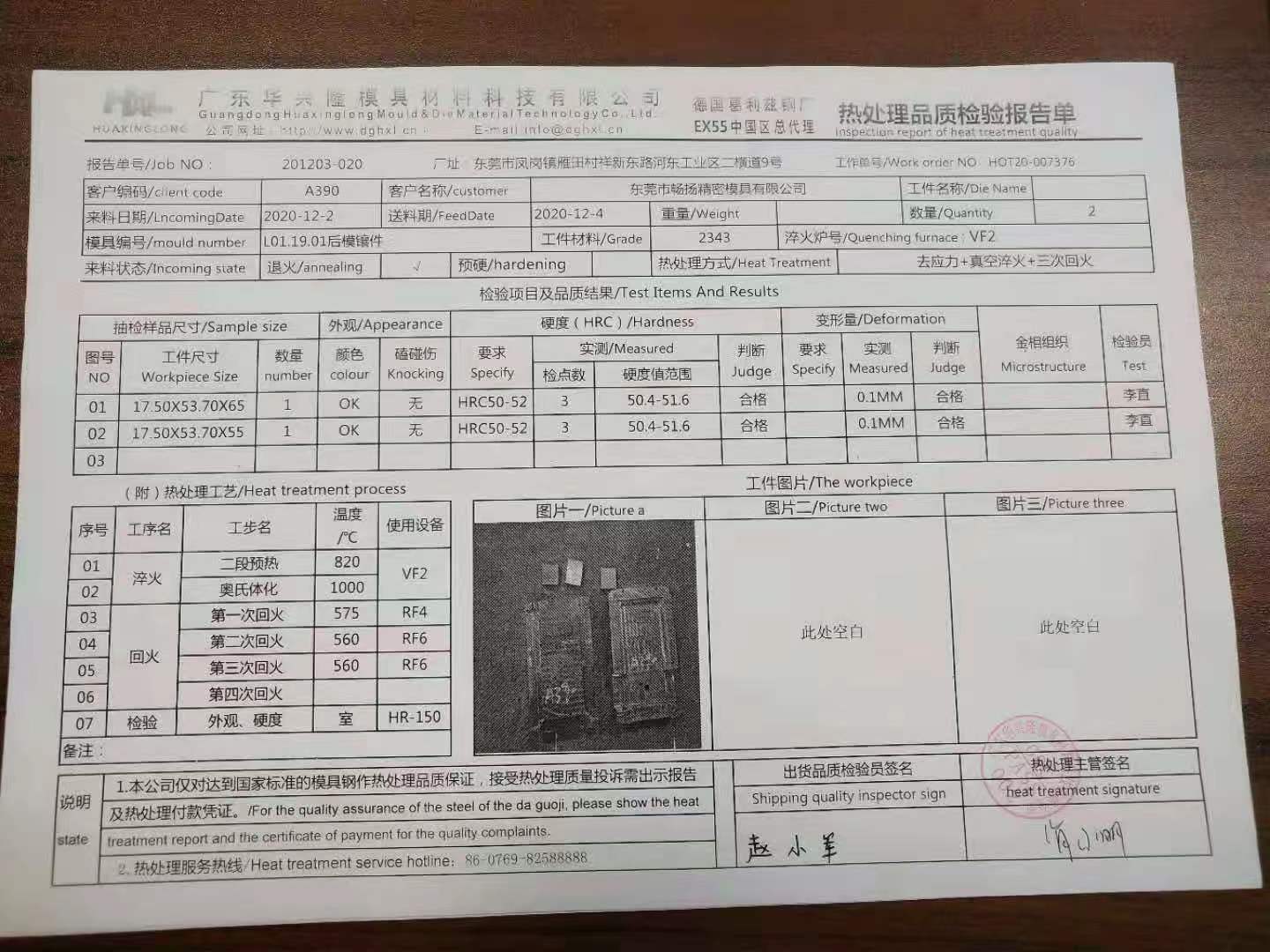
For the two inspected workpieces, the heat-treatment report specifies HRC 50–52 and records measured hardness values in the range HRC 50.4–51.6, marked acceptable on the report. It also records approximately 0.1 mm deformation for the inspected items. These are results for the workpieces identified in that report, not a universal mold acceptance statement. Material traceability should connect each certificate and inspection record to its corresponding component.
9.Machine Interface and Mold Installation
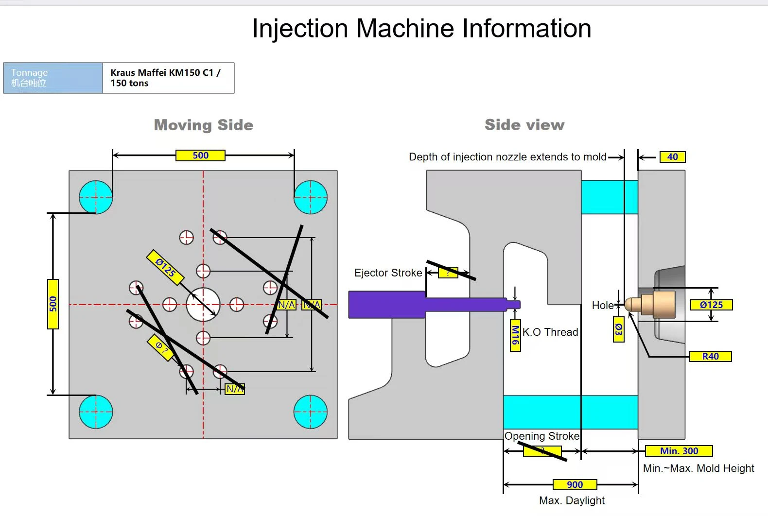
The machine-interface drawing identifies a KraussMaffei KM150 C1, 150-ton injection molding machine. It shows a 500 mm by 500 mm tie-bar spacing arrangement, a nozzle interface and ejection-related connection details. The drawing is a machine compatibility reference. It does not prove that all trials or production runs for this housing were completed on that exact press.
Before mold installation, the mounting plate arrangement, locating ring, nozzle reach, mold height, opening stroke and ejection interface should be checked against the press. The interface drawing shows a minimum mold-height reference of 300 mm and a maximum daylight reference of 900 mm. Actual mold dimensions and lifting weight should be confirmed from the final tool documentation before installation.
The tool should also be reviewed for cooling and hot-runner connections, safe movement of sliders, clamping clearance and access to service points. A pre-trial checklist is preferable to relying on the machine tonnage alone. Tonnage confirms only one aspect of compatibility; mold opening, injection capacity, tie-bar clearance and auxiliary systems may be equally limiting.
10.Tool Trial, Inspection and Production Control
A practical first trial for this housing should establish a stable filling window before dimensional corrections are considered. The team should check complete fill around the rectangular opening, visible weld or knit regions, flash at the parting line and slider shut-offs, and release of the side locking features. The condition of the broad panel should be reviewed for sink, distortion and handling marks.
Inspection should follow the customer-approved drawing. Priority features are likely to include mounting-hole locations, opening dimensions, overall envelope, local mating faces and the geometry of the locking features. This is a recommended inspection focus based on the visible geometry; it is not a claim that those features have a particular tolerance or that an inspection report was supplied for every one of them.
When a dimensional issue is found, the investigation should distinguish between tool geometry and process response. A change in packing or cooling may improve one area while moving another feature out of tolerance.
Dimensional samples should therefore be measured under a documented and repeatable process. Approved samples, revision-controlled CAD data and clear acceptance criteria are needed before serial production release.
11.Custom Housing Tooling and Molding Enquiries
For a comparable plastic housing, Deep Mould can review the CAD geometry, tooling approach and injection molding requirements. The initial review should include material grade, projected order quantity, functional interfaces, cosmetic surfaces, dimensional tolerances and any restrictions on gate position or ejector marks. A 3D STEP model and controlled 2D drawing are the preferred starting documents.
Where side locks or undercuts are present, the DFM review should identify the proposed parting line, slider direction, draft and shut-off conditions before the mold design is finalized. Where the geometry presents filling risk, Moldflow analysis can support the comparison of gate or runner alternatives. The resulting recommendations should be confirmed with the customer before the final tooling revision is released.
Related pages and engineering enquiry
Plastic Injection Molding Services - Deep Mould
Injection Mold Manufacturing and Company Capabilities - Deep Mould
Send the CAD model, drawing, PA66 or alternative resin specification and expected quantities to request a mold and molding review.
Hot Tags: Custom Plastic Housing Injection Molding, Custom Plastic Housing, PA66 Injection Molding, Plastic Housing Mold, Injection Mold Design
Send Inquiry
You Might Also Like